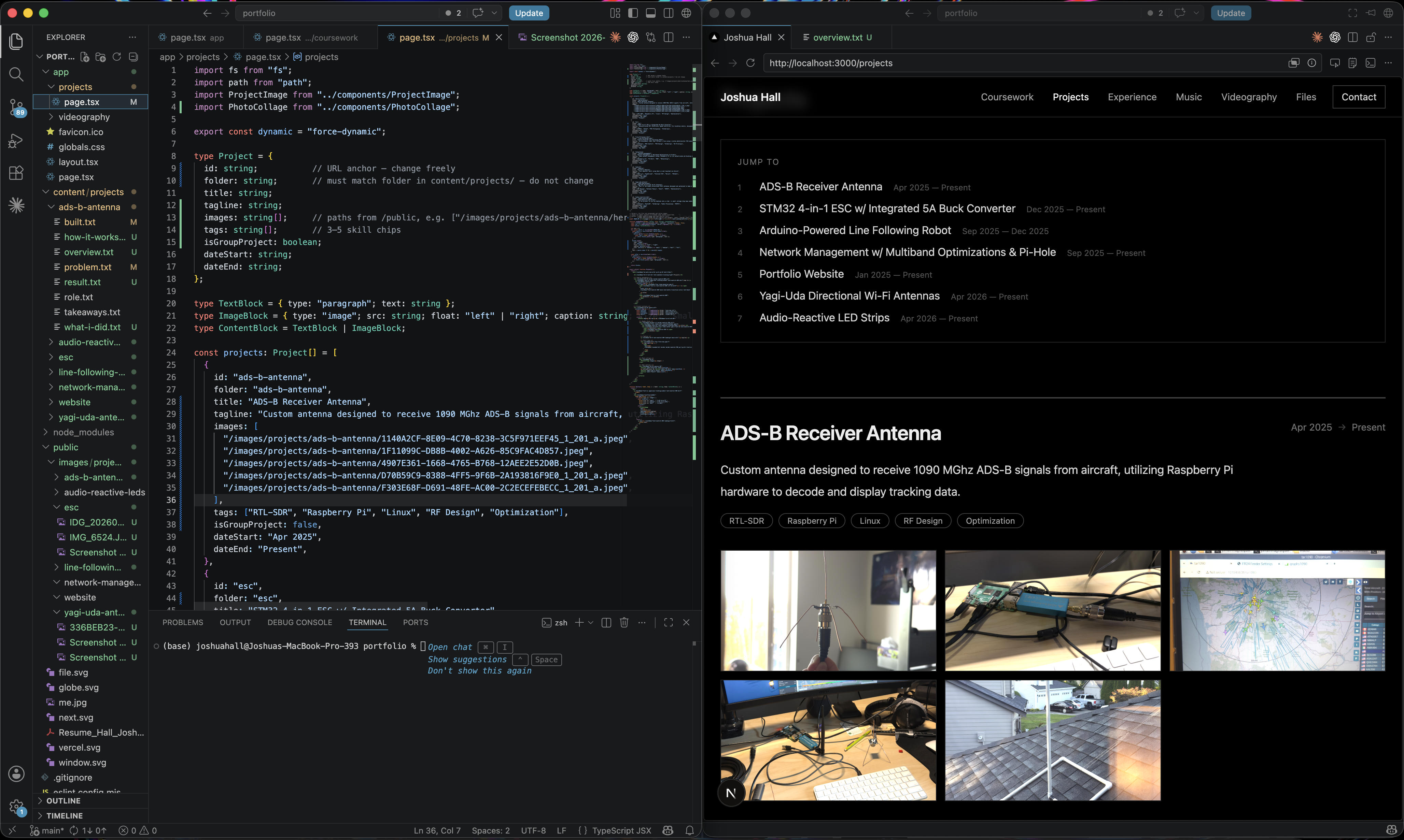
ADS-B Receiver Antenna
Apr 2025 — PresentCustom antenna designed to receive 1090 MHz ADS-B signals from aircraft, utilizing Raspberry Pi hardware to decode and display tracking data.
Overview
I consider this my signature project - one that I am certainly most proud of. During my freshman year my dorm was situated under the inbound/outbound flight path for SeaTac airport. I often used Flightradar24 to guess airplane models when they flew overhead, but I was curious if I could track them myself. No ads. No apps. My goal was to track airplanes 24/7 cost effectively and accurately.
How It Works
To start this project I researched how planes are even tracked in the first place. Flightradar24 tracks airplanes from every corner of the world… how? How does ATC manage the location of aircraft in extremely tense environments? The answer is ADS-B (Automatic Dependent Surveillance-Broadcast), a modern surveillance broadcasting system that replaces GPS. It is a highly-accurate broadcasting system that transmits aircraft location, speed, altitude, destination, type, and heading via a transponder mounted on the aircraft. These signals can be broadcast over two frequency bands, 1090 MHz and 978 MHz. My antenna is designed to read 1090 MHz, as that is the frequency most high-performance aircraft use. 978 MHz is mainly used for aircraft flying below 18,000ft.
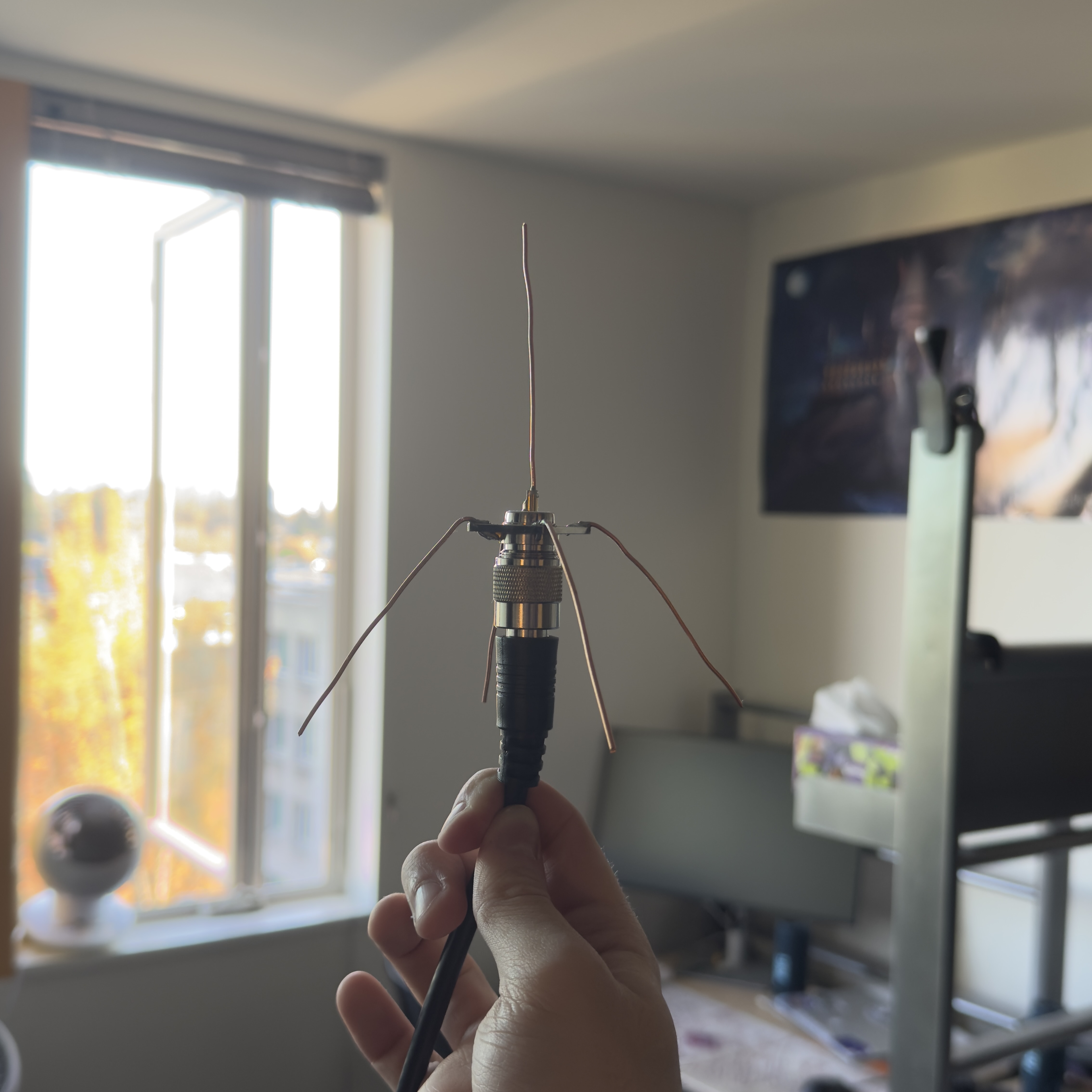
My antenna is called a quarter-wavelength antenna, consisting of 4 ground planes and one radial sticking straight up. Each prong is a copper wire cut to 69mm, which was determined using the wavelength formula:
To account for conduction losses in the wires due to thickness and soldering connections, wavelength is multiplied by 0.95 to get around 65mm. I didn’t think of this at the time of initial construction, so all of my radials are around 69mm. The antenna still performs great compared to other antennas I researched online. I will go more into performance optimization later, as some other fascinating changes drastically improved my performance.
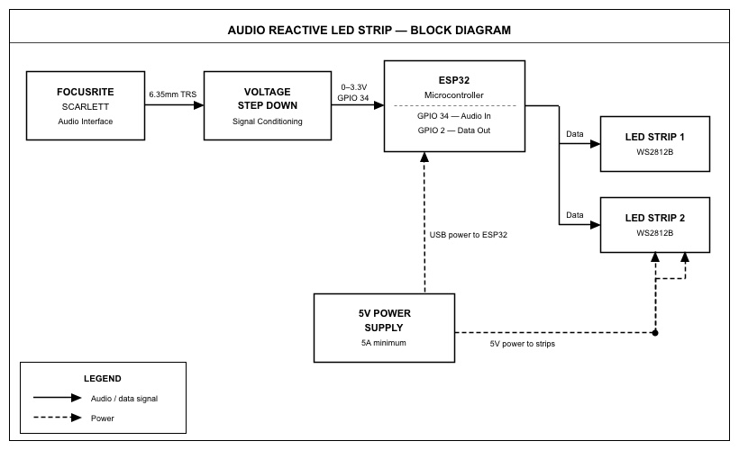
My antenna ‘core’ is an SO239 Female FR Coax connector, which screws on to the end of a coax cable and provides mounting holes on the four corners with a vertical element. These pieces are used for a wide variety of different antenna applications. This component provided an easy base that allowed me to connect a coax cable straight to my antenna. Next, via a 20ft RG8x coax cable, my data is then sent into an ADSBexchange RTL2832U 1090MHz filter. ‘Filter’ is the key word here, as this component is a bandpass filter that ensures any noisy frequencies from cell phones, TV’s, and FM radio don’t interfere with the data that my Raspberry Pi reads. Being in the University District, signal interference is a big deal. The RTL2832U is just a blue stick that plugs in via USB-A into my Pi and has a small coax male end. I used an adapter to connect my RG8x coax to the stick. I researched that these filters are basically required since they boost signal quality by so much. They were listed in almost every tutorial I researched. They are usually very expensive, so I ordered a cheaper one on amazon that doesn’t exist anymore and it seems to do the job. Last but not least, the brains of my operation, a Raspberry Pi 4B. This project was my first time using Raspberry Pi, and I had a blast setting it up and discovering what these little computers are capable of. Luckily for me, ADS-B antennas have a large community with plenty of open source software on github that makes setup (mostly) straightforward.
My data is acquired through the filter via USB and is first run through readsb, a popular decoding software. This turns whatever data that is passed through my filter into actual aircraft data that is readable. The output of this program can be a wicked-fast list of latitudes, longitudes, model numbers and speeds updating every second, but I wanted to visually see my tracked planes on a map, just like Flightradar24. At this point, my data junctions in two directions within my Pi. A program called tar1090 reads my readsb data and outputs my aircraft data on map with a convenient list of all aircraft currently tracked by my antenna, the number of aircraft currently tracked, and a messages/sec statistic that I used to test the performance of my antenna. The readsb data is also sent to a Flightradar24 program that allows hobbyists like me to send my tracking information to their app and enhance their tracking models, with a free business-tiered subscription as a reward. I discovered that I could do this during my software setup phase on the Pi, so it motivated me even more to enhance my data. At this point, I had a fully working antenna setup that read a specific frequency, decoded aircraft signals, and displayed them on a map that I could see in my dorm room 24/7.
For fun, I bought an old Dell XPS from 2015 off of a guy on facebook marketplace, gently tore out the screen, and used its LCD display as the main screen for my Pi so I could have a live map continually running in my dorm room for me and my roommate.
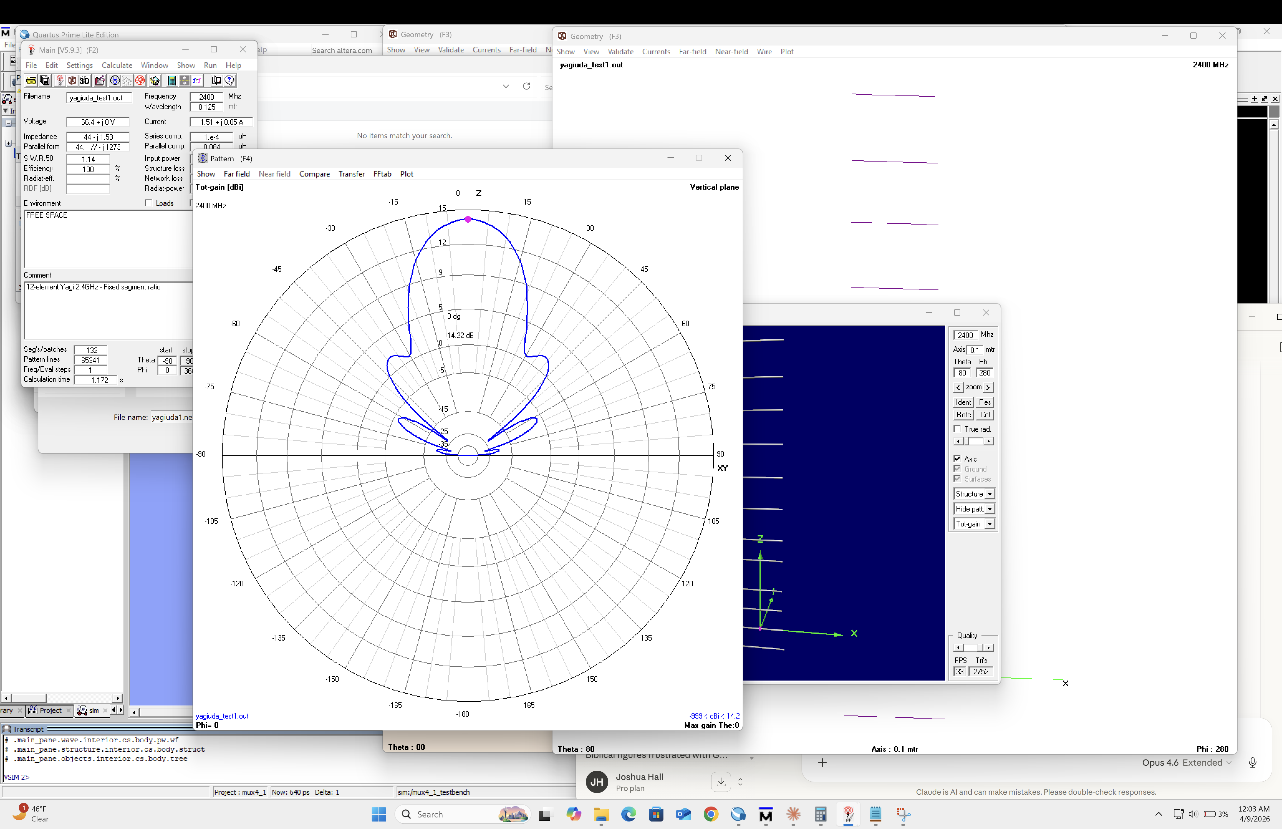
A large portion of this project was optimizing my setup to get the best possible messages/sec. This statistic was congruent with data quality, number of aircraft tracked, and range. More messages meant more planes and smoother updates. When I first got the software set up, I used a stock antenna that was shipped with my filter, and got around 15 msg/sec, which was quite low. This roughly translates to about 15 aircraft with ~20 miles of range. I plugged in my DIY antenna and that immediately jumped the messages to 60-80 with over 40 aircraft tracked simultaneously. This was because the stock antenna was just a vertical radial, it had no reflectors (the four ground planes on my antenna) that allowed better directionality. After lots of software research, physical positioning changes, and deeper research into what interferes with ADS-B signals, I discovered the following parameters that I adjusted to get optimal tracking quality.
- Physical space around the antenna was the single most important factor in data quality. This surprised me initially and I discovered this by accident. When I first plugged in my antenna, it was free to move around and only bound by the long coax cable, so the first thing I did was move the antenna right next to my window, and I discovered that the proximity to a solid surface decreased the quality of my data. If I held the antenna in the center of my dorm room away from walls, I acquired better data. When I returned home for the summer, I built a mount out of PVC pipes to put the antenna on the roof of my house. Since the antenna was out in open air with a clear view of the sky, I was able to track planes all the way south to Portland, OR, and north to Vancouver, BC. This was where I acquired my best data: 258 messages/sec with over 150 nautical miles of range.Within readsb there is a digital gain parameter that boosts or quiets incoming ADS-B signals into my antenna. My understanding of the parameter is like this: my antenna is like a microphone and nearby aircraft are emitting a sound (not engine noise, but their ADS-B data) at a certain volume. If the aircraft is further away, its sound is quieter. If it's closer, it's louder. The digital gain parameter is essentially turning up the sensitivity of my ‘microphone’ which records the ADS-B ‘sounds’. The higher the gain, the louder distant signals are, but so are closer signals. If my gain was too high, nearby aircraft would blast my antenna with huge amounts of noise, causing my messages/sec to skyrocket and clip the data coming in, causing the data to be unreliable and sometimes unreadable. I attenuated my gain so I could get more range without clipping nearby signals.Geographical location is the last optimization that had a large impact on my performance. This parameter, however, was the hardest to change because where I lived greatly impacted the performance of my antenna. In the dorms, I had a fantastic view south with minimal obstructions, so I was able to reach Oregon from my dorm. But since I was at the south edge of the building, I wasn't able to track much further than 10 miles north of my dorm. At home, which is 45 minutes southeast of Seattle, gave me the best performance because of the open air. Both of these locations had Mt. Rainier impact tracking performance, as tar1090 showed my range would drop out just around the mountain due to its size. Long story short - clear, open, flat views provided the best performance.
Result
I’ve learned a lot from working on this project and iterating on it over time. I discovered the general workings of how antennas work, aircraft communication, how to use Raspberry Pi hardware and software, and most importantly: troubleshooting. Throughout the entire course of the project I was constantly researching and using AI to find solutions to bad data or malfunctioning software on my Pi. The project was a lot of trial and error, most of it was brute forcing though software setups and not understanding how they worked, but over time I learned how to dissect where my errors originated more efficiently. Lastly, I acquired a free business tier subscription for sending my tracking data to FlightRadar24 which unlocks a plethora of tracking features. I also discovered a lot about aircraft routes in the area (SeaTac flips which directions planes land and takeoff based on weather and time of day), busiest airspace times (about 4pm), and when certain aircraft fly over my location every day.
Updates
Antenna offline for 2 months. Establishing a new location to mount the antenna indoors and establish connection with Flightradar24 and begin collecting Graphs1090 data.